The pain point of photovoltaic mc4 connector installation: Crimping
With the rapid development of the distributed, especially household photovoltaic market in recent years, the quality problems of photovoltaic systems have become more and more prominent. A fire in a photovoltaic system will not only endanger personal safety, but also have a negative impact on the industry. According to foreign research reports, connector mutual insertion and irregular connector installation rank the first and third causes of fire. This article focuses on the analysis of the irregular installation of connectors, especially the crimping of the photovoltaic cable and the connector metal core, in order to provide users with a certain reference, maintain the photovoltaic system, and protect the benefits of users.
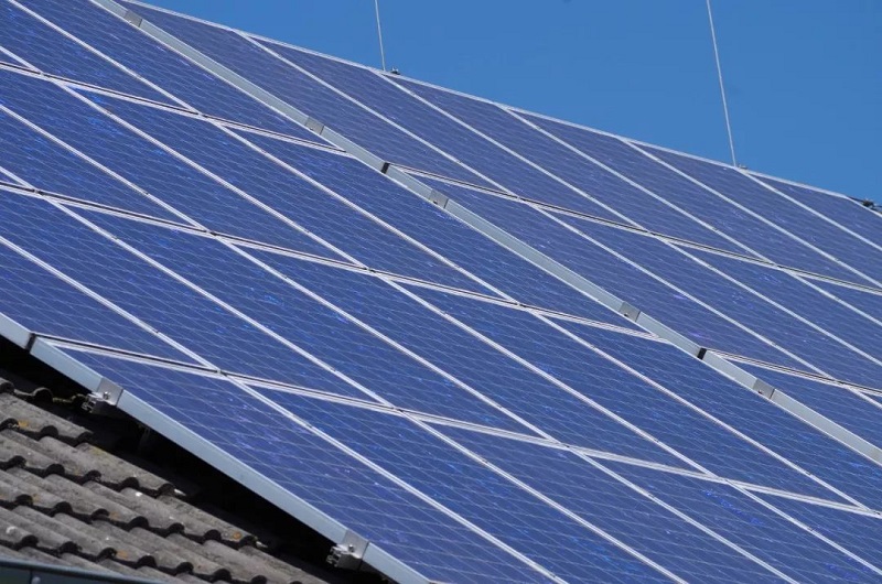
Market Situation
In a photovoltaic power generation system, photovoltaic connectors are mainly used in components, combiner boxes, inverters and the connections between them, most of which are installed in the factory, and the crimp quality is relatively reliable. About 10% of the remaining connectors need to be manually installed at the project site, mainly referring to the need to install connectors at both ends of the photovoltaic cable connecting each device. According to the experience of many years of customer visits, due to the lack of training of on-site installation workers and the use of professional crimping tools, crimping irregularities are common, as shown below.
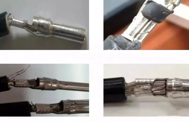
[Figure 1: Irregular crimping case]
Types and characteristics of metal cores
The metal core is the main body of the connector and the most important flow path. At present, the vast majority of photovoltaic connectors on the market use a “U”-shaped metal core, which is stamped and formed from a copper sheet, also known as a stamped metal core. Thanks to the stamping process, the “U”-shaped metal core not only has high production efficiency, but also can be arranged in a chain, which is very suitable for automated wire harness production.
Some photovoltaic connectors use an “O”-shaped metal core, which is formed by drilling holes at both ends of a thin copper rod, which is also called a machined metal core. The “O”-shaped metal core can only be crimped individually, which is not suitable for use in automated equipment.
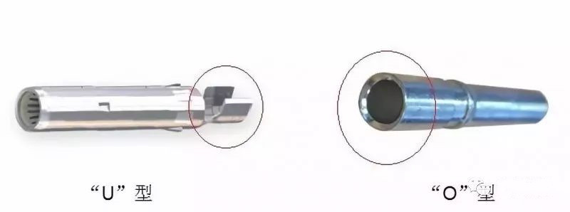
【Picture 2: Metal core type】
There is also an extremely rare metal core that is crimp-free, which is connected to the cable by a spring sheet. Since no crimping tools are required, installation is relatively simple and convenient. However, the connection of the spring leaf will result in a large contact resistance, and long-term reliability cannot be guaranteed. Some certification bodies also do not approve this kind of metal core.

[Table 1: Features of different metal cores]
Basic knowledge of crimping
Crimping is one of the most basic and common connection techniques. Countless crimping occurs every day. At the same time, crimping has been proven to be a mature and reliable connection technology.
Crimping process
The reliability of crimping depends largely on tools and operations, both of which determine whether the final crimping effect meets the requirements of the standard. Take the “U”-shaped metal core as an example. It is basically a copper tin-plated material and needs to be connected to the photovoltaic cable by crimping. The crimping process is as follows:
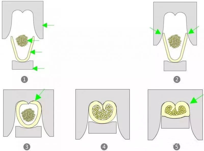
【Picture 3: Crimping process】
It is not difficult to see that the “U”-shaped metal core crimping is a process in which as the crimping height gradually decreases (while the crimping force gradually increases), the copper sheet wrapped with the cable copper wire is gradually compressed. In this process, the control of crimping height directly determines the quality of crimping. The control of the crimp width is not very important, because the crimp die determines the width value.
Crimp height
Many people know that crimping too loose or too tight is not good, so as the crimping progresses, how much should the crimping height be controlled? In addition, how do two important quality indicators, namely pull-off force and electrical conductivity, change during this process?
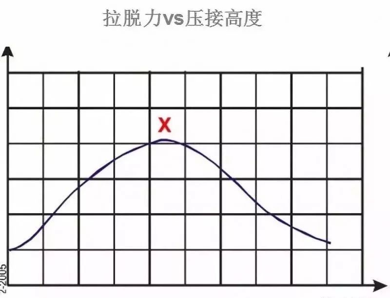
[Figure 4: Pull-off force and crimp height]
As the crimping height gradually decreases, the pull-off force between the cable and the metal core will gradually increase until it reaches the “X” point in the figure above. If the crimping height continues to decrease, the pull-off force will continue to decrease due to the gradual destruction of the structure of the copper wire.
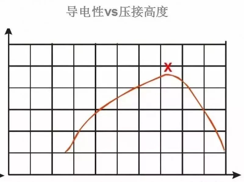
[Figure 5: Conductivity and crimp height]
The figure above describes the long-term electrical characteristics of crimping. The larger the value, the better the electrical conductivity, and the better the electrical characteristics of the cable and metal core connection. “X” represents the best point.
If the above two curves are superimposed together, we can easily get a conclusion:
Thebest crimping height can only be a comprehensive consideration of pull-off force and conductivity, and a value in the area between the two best points, as shown below.
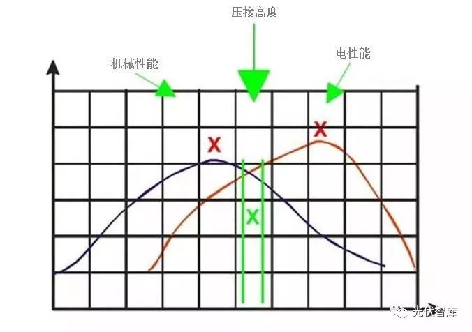
[Figure 6: Crimp height, mechanical and electrical properties]
Crimping quality evaluation
The judgment methods commonly used in the industry are as follows:
■ The crimping height/width can be measured with a vernier caliper within the defined range;
■ Pull-off force, that is, the force required to pull or break the copper wire from the crimping place, such as 4mm2 cable, IEC 60352-2 requires at least 310N;
■ Resistance, taking the 4mm2 cable as an example, IEC 60352-2 requires the resistance at the crimp to be less than 135 microohms;
■Cross-section analysis, non-destructive cutting of the crimping zone, analysis of width, height, compression rate, symmetry, cracks and burrs, etc.
If it is to release a new device or a new crimping die, in addition to the above points, it is also necessary to monitor the resistance stability under temperature cycling conditions, refer to the standard IEC 60352-2.
Crimping tool
The vast majority of photovoltaic connectors are installed in the factory through automated equipment, and the crimp quality is high. However, for connectors that have to be installed at the project site, crimping can only be done with crimping pliers. The original professional crimping pliers must be used for crimping. Ordinary vise or needle-nose pliers cannot be used for crimping. On the one hand, the quality of crimping is low, and this is also a method not recognized by connector manufacturers and certification agencies.
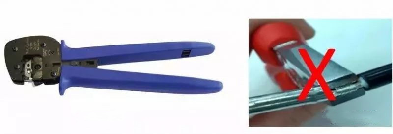
【Picture 7: Crimping tool】
Irregular crimping hazards
Poor crimping may lead to non-compliance with specifications, unstable contact resistance, and sealing failure. It is a big risk point that affects the overall function and profitability of photovoltaic power plants.
Summary
■ The connector is a small part, but it will affect the operational efficiency of the photovoltaic project. Compromise with quality usually means high subsequent losses and risks, which could have been avoided;
■ For the installation of photovoltaic connectors, the crimping link is the most important, and it is recommended to use professional crimping tools. For engineering installers, crimping training is an indispensable link.